40 Results
View results:
Sort by:

Using an example of a steel fiber-reinforced concrete slab, this article describes how the use of different integration methods and of a different number of integration points affects the calculation result.

When a concrete slab is set upon the top flange, its effect is like a lateral support (composite construction), preventing problems of torsional buckling stability. If there is a negative distribution of the bending moment, the bottom flange is subjected to compression and the top flange is under tension. If the lateral support given by the stiffness of the web is insufficient, the angle between the bottom flange and the web intersection line is variable in this case so that there is a possibility of distortional buckling for the bottom flange.

As you may already know, RFEM 6 offers you the possibility to consider material nonlinearities. This article explains how to determine internal forces in slabs modeled with nonlinear material.

The properties of the connection between a reinforced concrete slab and a masonry wall can be correctly considered in the modeling using a special line hinge that is available in RFEM 6. This article will show you how to define this type of hinge using a practical example.

The optimal scenario in which punching shear design according to ACI 318-19 [1] or CSA A23.3:19 [2] should be utilized is when a slab is experiencing a high concentration of loading or reaction forces occurring at one single node. In RFEM 6, the node in which punching shear is an issue is referred to as a punching shear node. The causes of these high concentration of forces can be introduced by a column, concentrated force, or nodal support. Connecting walls can also cause these concentrated loads at wall ends, corners, and ends of line loads and supports.

According to EN 1992-1-1 [1], a beam is a member of which the span is no less than 3 times the overall section depth. Otherwise, the structural element should be considered as a deep beam. The behavior of deep beams (that is, beams with a span less than 3 times the section depth) is different from the behavior of normal beams (that is, beams with a span that is 3 times greater than the section depth).
However, designing deep beams is often necessary when analyzing the structural components of reinforced concrete structures, since they are used for window and door lintels, upstand and downstand beams, the connection between split-level slabs, and frame systems.

In accordance with Sect. 6.6.3.1.1 and Clause 10.14.1.2 of ACI 318-19 and CSA A23.3-19, respectively, RFEM effectively takes into consideration concrete member and surface stiffness reduction for various element types. Available selection types include cracked and uncracked walls, flat plates and slabs, beams, and columns. The multiplier factors available within the program are taken directly from Table 6.6.3.1.1(a) and Table 10.14.1.2.

The punching shear design, in line with EN 1992-1-1, should be performed for slabs with a concentrated load or reaction. The node where the design of punching shear resistance is performed (that is, where there is a punching problem) is called a node of punching shear. The concentrated load at these nodes can be introduced by columns, concentrated force, or nodal supports. The end of the linear load introduction on slabs is also regarded as a concentrated load and therefore, the shear resistance at wall ends, wall corners, and ends or corners of line loads and line supports should be controlled as well.

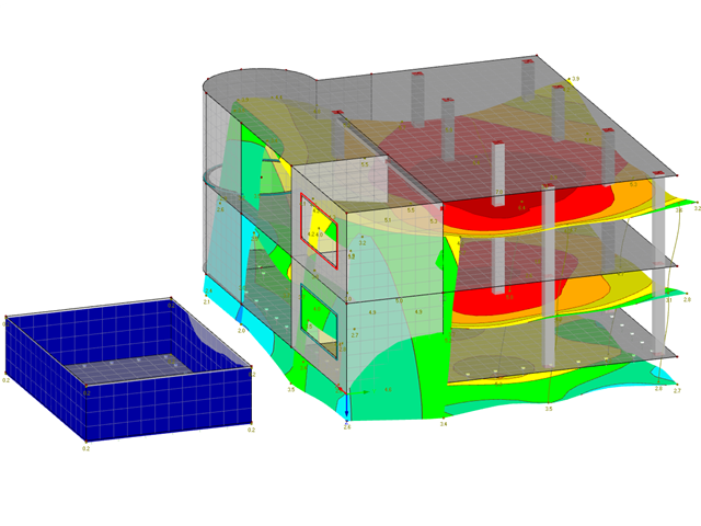
This article describes how a flat slab of a residential building is modeled in RFEM 6 and designed according to Eurocode 2. The plate is 24 cm thick and is supported by 45/45/300 cm columns at distances of 6.75 m in both the X and Y directions (Image 1). The columns are modeled as elastic nodal supports by determining the spring stiffness based on the boundary conditions (Image 2). C35/45 concrete and B 500 S (A) reinforcing steel are selected as the materials for the design.

When modeling structural bearing systems, especially hall structures, some substructures of a foundation with no influence on the rising structure are not modeled in RFEM/RSTAB. In the case of hall structures, these are, for example, reinforced concrete floor slabs, strip foundations, and the ties between column foundations.

You can use the "Free Circular Load" option in RFEM to apply a partial uplift force to a cone‑shaped floor slab. It can be defined as linearly variable. The definition of center C and the outer boundary R can be specified easily, using the select function.

In RF‑/FOUNDATION Pro, the reinforcement to be placed in the foundation slab and, if necessary, the bucket links, is displayed in a 3D rendering and in the reinforcement drawings.

In the RF-/FOUNDATION Pro add-on module, you can select the automatic dimensioning of the foundation plate geometry. In the dialog box for the design parameters of the foundation plate, you can, for example, specify the increment for the increase of the base area and the foundation plate thickness. You can also automatically increase the covering for a stabilizing effect of the geotechnical designs.

Concrete on its own is characterized by its compressive strength. An important part of reinforced concrete is reinforcing steel, which contributes to both the compressive and the tension resistance of the concrete. Welded wire fabric is generally located in the tension areas of the beams or surface elements (hollow core ceiling, wall, shell) to transfer the tensile forces induced by external loading.

In the RF‑/HSS add‑on module, you can analyze the connections for nodes at which hollow sections join. RF‑/HSS performs the ultimate limit state designs according to EN 1993‑1‑8:2005.
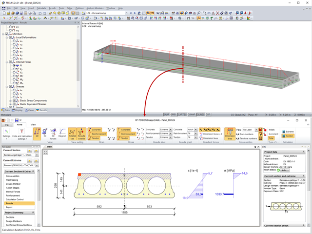
Prestressed concrete slabs consist of composite, uniaxially stressed hollow plates with a width of about 1.20 m. These elements are prestressed with pre-tension in a precast concrete plant. The precasting is usually done with slipformers. Due to the lesser self‑weight of the non‑solid slab and the existing prestress, these precast prestressed hollow core slabs show a lower deflection than loosely reinforced slabs made of solid concrete.

When defining the effective slab width of T-beams, RFEM provides the predefined widths that are determined as 1/6 and 1/8 of the member length. A more detailed explanation on these two factors is given below.

Closed circular cross-sections are ideal for welded truss structures. The architecture of such constructions is popular when designing transparent roofs. This article shows the special features of the connection design using hollow sections.
Settlement within a structural system can also affect the surrounding structures. The adjacent settlement of separated slabs can be considered with RF-SOILIN using a small trick.

Describing the procedure for the serviceability limit state design of a floor slab made of steel fiber reinforced concrete. This article shows how to perform the corresponding design for the SLS by means of the iteratively determined FEA results.

Reinforced concrete surface design for slabs, plates, and walls is possible in the RF-CONCRETE Surfaces module according to the ACI 318-19 or the CSA A23.3-19 standard. A common approach for slab design is the use of design strips for determining the average one-way internal forces over the width of the strip. This design strip method essentially takes a two-way slab element and applies a simpler one-way approach to determine the required reinforcement needed along the strip length.

Steel-fiber-reinforced concrete is mainly used nowadays for industrial floors or hall floors, foundation plates with low loads, basement walls, and basement floors. Since the publication in 2010 of the first guideline about steel-fiber-reinforced concrete by the German Committee for Reinforced Concrete (DAfStb), a structural engineer can use standards for the design of the steel fiber-reinforced concrete composite material, which makes the use of fiber-reinforced concrete increasingly popular in construction. This article describes the nonlinear calculation of a foundation plate made of steel fiber-reinforced concrete in the ultimate limit state with the FEA software RFEM.
When performing control calculations and comparing the internal forces and the resulting required reinforcement of downstand beams, large differences can occur. Although the same load assumptions and spans are applied, some programs or the manual calculation display very different internal forces compared to the FEA model. The differences already occur in the case of the centric member and without considering the internal forces' components from the possible effective slab widths.

In accordance with Sec. 6.6.3.1.1 and Sec. 10.14.1.2 of ACI 318-14 and CSA A23.3-14, respectively, RFEM effectively takes into consideration concrete member and surface stiffness reduction for various element types. Available selection types include cracked and uncracked walls, flat plates and slabs, beams, and columns. The multiplier factors available within the program are taken directly from Table 6.6.3.1.1(a) and Table 10.14.1.2.

A site joint consisting of hollow sections with end plates will be designed. It is the bottom chord of a truss that has to be divided for transport reasons.

The stiffening of timber structures is usually carried out by means of timber panels. For this purpose, structural components consisting of slabs (chipboard, OSB) are connected with members. Several articles will describe the basics of this construction method and the calculation in the RFEM program. This first article describes the basic determination of the stiffnesses as well as the calculation.

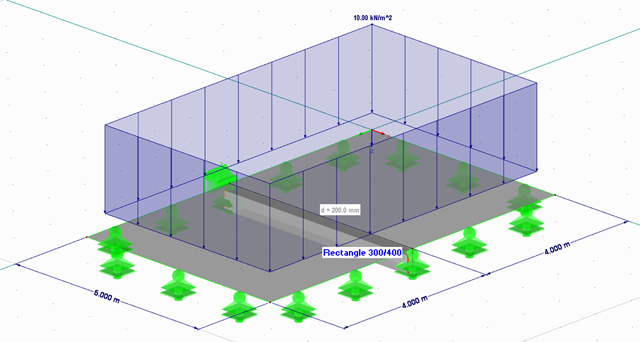
This article describes how a flat slab is generated as a 2D model in RFEM and the loading is applied according to Eurocode 1. The load cases are combined according to Eurocode 0 and calculated linearly. In the RF-CONCRETE Surfaces add-on module, the bending design of the slab is performed while taking into account the standard requirements of Eurocode 2. The reinforcement is complemented by a rebar reinforcement for areas that are not covered by the mesh basic reinforcement.
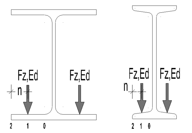
For suspension cranes, the bottom chord of the runway girder is subjected to local flange bending due to the wheel loads in addition to the main load-bearing capacity. The bottom chord behaves like a slab due to these local bending stresses, and has a biaxial stress condition [1].
Using RF-/FOUNDATION Pro, it is possible to perform geotechnical design according to EN 1997-1 [1] for single foundations. The following article explains the design of highly eccentric loading in the foundation core according to DIN EN 1997‑1, A 6.6.5 (see [3]).
![Design Model for Bonded Joint Resistance According to [1]](/en/webimage/009526/2419234/01-en-png.png?mw=640&hash=c76563b459152b19c98197ea6ba342be89d9a5bc)
In the construction process, it is often necessary to fabricate the concrete elements in sections. A classic example of this production in sections is the use of prefabricated downstand beams, in which the slab is completed in the onsite concrete construction. By creating a new concrete area, interfaces may arise between the already hardened concrete and the fresh concrete. The transfer of the longitudinal shear forces arising between the partial cross-sections must be considered in the design.